Returned and Reviewed Midterm:
I returned the midterms, and asked if anyone had questions. There wasn't much discussion.
Class work:
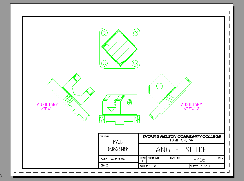
Of the pages I allowed the next assignment to come from, the class voted to work on the 3D modeling and Paper Space viewport (auxiliary view) problem at the bottom of page 416, FIG 12-_ _, the Angle Slide. I completed at least 3/4 of the assignment while explaining what I was doing, during class. Most of the class followed along with me. I showed the class (again):
BOX to make solid boxes, to later UNION or SUBTRACT
EXTRUDE (positive or negative)
CYLINDER (or EXTRUDEing a circle)
UNION to merge (weld) solids together
SUBTRACT to take away from the big solid, the smaller object
FILLET to round out concave or convex corners. Don't worry if you can't FILLET all that are shown in the book. I STILL can't figure how to do them all. Just do a few.
UCS creation and saving (3 point and Z-axis Rotate) Note: to develop the Auxiliary views, first use UCS Z Axis Rotate option to rotate the UCS 45 degrees (or 135 degrees) one way or the other, then establish the PLAN view, then save the resulting View. Later, restore that saved View while within the Viewport, while in Paper Space.
Setting the system variable WORLDVIEW to 0, using the pulldown menu View>3D Views>Viewpoint Presets> and checking the "Relative to UCS" radio button. Later I learned to simply type WORLDVIEW (enter) 0 (enter).
PLAN to generate a "top" view in accordance with the current UCS, as if you're looking straight down to the X-Y plane.
Views, saving and restoring
starting Paper Space (by clicking on "Layout 1" at the bottom of the screen), click OK to accept the defaults, and erase the single default big viewport.
INSERTing a title block drawing (ASIZE.dwg) on Layer zero
MVIEW, Viewports creating (from Rectangles and Circles, with Object option)
Scaling the display in the viewports. Each viewport should have the same "zoom scale". To do so, double click in each Viewport, type Z (enter) .5xp (enter). This makes the final printout of the object, 1/2 the scale of the ASIZE (10 by 7.5) border.
Aligning the
views can be easily done by moving the viewports (not PANning), using construction
lines and osnaps, while in Paper Space (the Layout tab).
Did I forget anything?
This assignment is due in two more weeks, on November 6th.
Handouts: Nothing
Due next class: Nothing
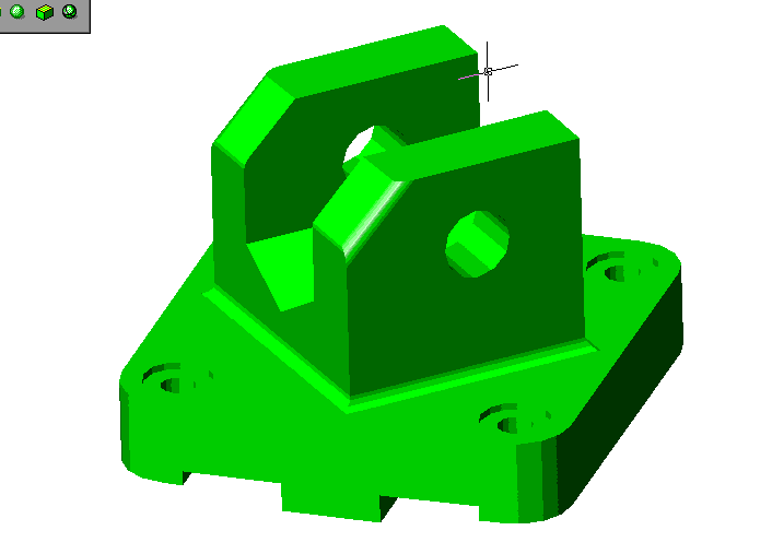
Due in two weeks: Page 416, Bottom, Figure ___, the Angle Slide, as described above. See the screen capture below for my completed example. Be aware that it might not print out "hidden". That's OK.
Heads Up:
Next class (I expect) we'll start into dimensioning. I'll show you
how to save the dimvar settings (once you've got them all adjusted)
as "Dimension Styles". We'll have another CAD assignment where
at least two separate Dim Styles are required. Maybe it'll be a drawing with two or three parts on it. One part might be a
tiny object requiring fractions for the dimensions. Another part might be huge requiring dots for the terminators, and 2 decimals in the dimensions.
You'd then need a dim style to use for each part, and show each part in a
separate floating viewport, with ASIZE.dwg surrounding them. Maybe.
Soon after (maybe in a couple weeks), we'll get into various
types of tolerances. You might care to read (skim) ahead
Chapter 7, beginning on page 171, and chapter 26,
beginning on page 529. We'll likley learn "limits", "deviation",
and geometric tolerances with AutoCAD. Be aware we'll only
have a day or two of tolerancing. We really can't
cover it well in such little time.