4. In the floppy files list, click and hold the mouse button on the file that’s due today. 5. “Slide” the file over into the left side window (probably C:/Temp/Burgener/…), and release your mouse button.
6. Now rename the copy of your file, to your last name. Click once on the fresh copy of your file. Count to 2, and click a second time (or right-click and choose “Rename”). The blue partial highlighting indicates it’s waiting for you to type in your last name, like “WILSON.dwg”.
7. Double check the ‘.dwg” remains in the new file name.
8. Ordinarily you'd pull out your floppy, but this week please click and drag a copy of the file "ASIZE.dwg" from the hard disk to your floppy. We'll learn how to insert this titleblock and border drawing into (on top of) your drawings.
9. Remove your floppy.
Returned homework: Nothing
AutoCAD commands and concepts students should be familiar with AFTER this lesson:
INSERT (again) for "merging" another drawing with your "working" drawing. Later we'll learn how to use INSERT for applying standard symbols (BLOCKs).
EXPLODE (again) to "blast" INSERTed drawings into editable pieces. You can EXPLODE it WHILE INSERTing it, or afterwards.
BOUNDARY for making a polyline around the perimeter of an area.
BHATCH for cross hatching full- and half-section views
Opening more toolbars. From the Pull-down menu View, select Toolbars and check the ones you wnat to open. Another easiler way is to right-click on any icon.
HATCHEDIT to revise existing hatching. Note: HATCHEDIT is on the Modify II Toolbar.
Docking and Floating and closing Toolbars.
SOLID hatch pattern, to "spray paint" entire area one color.
SOLID for making quick arrow heads.
FILL toggle on and off (REGEN if necessary) to see and hide your Polyline and SOLID areas.
If time allows: Very Basic 3D viewing,
View Toolbar icons,
VPOINT,
Presets,
PLAN (type W for World UCS),
UCS (very briefly- we'll study better later),
UCSicon versions,
HIDE,
REGEN (review),
3D Orbit, (use the 3D Orbit's Zoom and Pan)
View>Shade>2D Wireframe, etc.
We'll look at sample drawings of solid and surface models.
If time allows we'll cover Chapter 8 (pages 233 to 247) of the green textbook on sectioning.
NEW NOTES ADDED OCTOBER 9TH:
P233, section views, different cross hatching patterns show different materials, if it's necessary.
p235, top show centerlines, but not hidden lines
p235, ll, "full section" looks like ½ is removed
p235, lr, patterns for general purpose or cast iron (ANSI31), and steel (ANSI32)
p236, ll, crosshatching lines should be neither parallel nor perpendicular to edges
p237, ll, thin items, such as gaskets can be drawn solid, and probably should be for economy.
P238, "half section" looks like ¼ of the object is removed.
p240, cr, nuts, bolts, pins, rivets, shafts, etc are not crosshatched in section views
p240, gaskets may shown as solid
p240, on adjacent parts, draw the cross hatching pattern angle so the parts contrast. Cross hatching lines for different parts should be perpendicular.
p241, offset section view. Don’t show where section line "bends"
p242, ribs aren’t crosshatched (typically)
p242, "lie" a bit for section views of symmetric items. Show as if it’s got even number of holes, even iif it’s really an odd number. Rely on the "front" view to show the truth.
P244, "revolved" sections for long parts or "ring" parts easily show the shape. "Removed" (broken) is an optional way to illustrate cross sections, without needing more paper space.
p245, Section views are best placed in line with the section plane line, much like orthographic views are arranged.
P246, ur, "broken out" sections show sectioning just for area of importance
Someplace I also covered the machining terms "fillet" (concave), and "round" (convex). Either of these curved surfaced are made with AutoCAD's FILLET command, for 2D work (Fillet also works on 3D solids).
Priority of lines (review, if time allows)
Solid, Hidden, Center. When different linestypes "superimpose" with a solid (continous) line, the solid line is the one to show on the final printout.
Centerlines that "superimpose" with a solid line? Show the visible line. Some textbooks suggest a "tick" to show there's a center line under it.
Hidden lines that "superimpose" with a solid line should show the solid (visible) line.
When a Hidden line is "superimposed" on a Center line, the Hidden line should be shown. Again, little "ticks" of the centerline may extend out past the hidden line.
Warning: Quiz next week!!
Quiz MAY (probably will) have Page 27 or 26-ish "complete the
orthographic views" puzzles, AutoCAD practical project, and/or AutoCAD multiple choice questions. See previous webpages for list of AutoCAD Commands and their respective pages in the text book and Instant Reference book.
What are fair questions for the quiz? What AutoCAD procedures are fair for the practical portion?
Assignments due next class:
Handout Page 26 of orthographic "complete the views"
puzzles.
Topics for next class (after quiz):
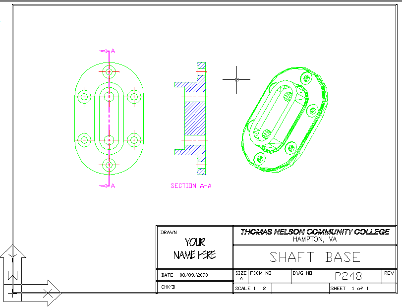
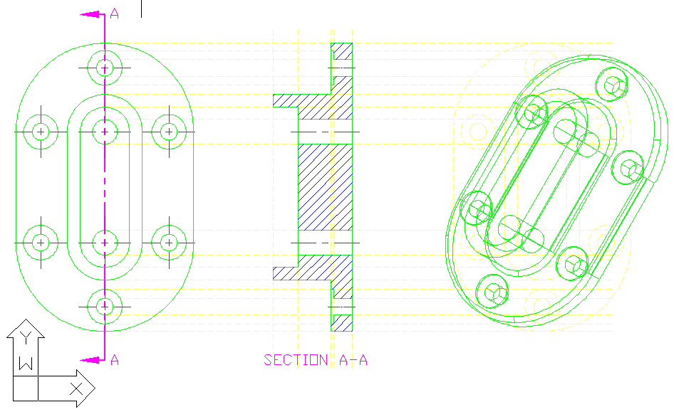
To complete the solid model shown below (Page 248), we'll learn 3D modeling commands: EXTRUDE, UNION, SUBTRACT, FILLET, ROTATE3D, after the quiz.
Assignments due in two more weeks:
AutoCAD 2D and 3D Solid, Page 248, FIG. 8-1-B, Shaft Base, including full-section, and solid model, as shown below. Use 1/16 for spotfaces. Egnore surface finishes. After tonight's class you SHOULD be able to make the full-section view. Wait until after next class (see topics above) to start the solid object.


Warning: The Midterm will likely be on the 8th week.